![Zendex-1.jpg]](https://41353989.hs-sites.com/hs-fs/hubfs/Zendex-1.jpg?width=40&height=40&name=Zendex-1.jpg)
Parts & Tools
Parts
- 2009-GRIP – Cam lever grip
- 2009-BOLT – Cam lever bolt
- 2009-ARM – Yellow cam arm
- 2009-WASHER – Black nylon spacer washer
- 2019 (GoJak Cotter Pin)
Tools
- 1/4" Allen key – for grip and bolt removal/installation
- 3/16" Allen key or 3/16" socket – for caster plate mounting bolts
- Diagonal cutting pliers (dikes) – for the cotter pin
- Channel-lock pliers – for moving the torsion spring
- Small hammer – for tapping pins into position
Repair A: Replacing the Grip and Bolt (Simple Swap)
Use this procedure if only the 2009-GRIP and 2009-BOLT need to be replaced and the yellow cam arm is undamaged.
Preparation
- Place the directional lever in the up position.
- Bring the pedal down and engage the pedal lock. This stabilizes the assembly and makes the cam mechanism easy to access.
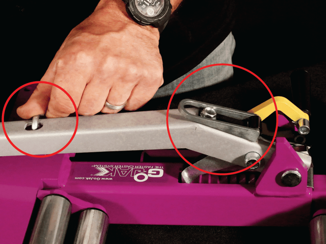
Fig. 1 – Lever up and pedal lock engaged (0:38)
Removal
3. Using a 1/4" Allen key, unthread the 2009-BOLT from the cam assembly.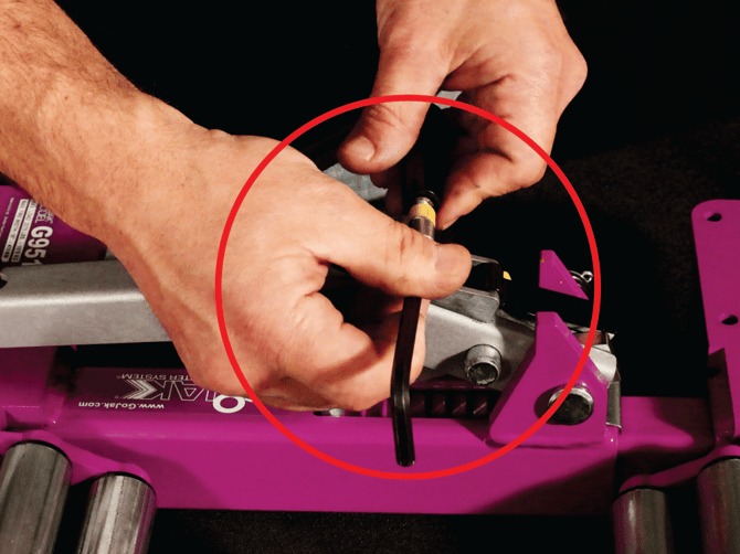
Fig. 2 – Removing the cam bolt with a 1/4" Allen key (1:05)
Installation
4. Position the new 2009-GRIP and 2009-BOLT on the 2009-ARM.
5. Ensure the bolt sits on TOP of the directional lever before threading it in.
Critical: The bolt MUST sit on top of the directional lever. When the unit is in operation and the directional lever is flipped to the down position, it must carry the cam lever with it. If the bolt is positioned incorrectly, the cam mechanism will not function properly.
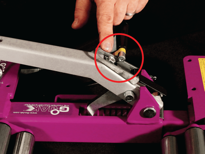
Fig. 3 – Bolt correctly positioned on top of the directional lever (1:15)
Repair B: Full Replacement (Arm, Washer, Grip & Bolt)
Use this procedure if the 2009-ARM (yellow cam arm) is bent or broken, and/or if the 2009-WASHER (black nylon spacer washer between the arm and pin) is missing or damaged.
Note: The nylon spacer washer is critical. A missing washer must be replaced as part of this repair.
Preparation
6. Place the go-jack in the up position.
7. Flip the cam lever and engage the pedal lock to keep the assembly steady.
8. Remove the casters using a 3/16" Allen key or 3/16" socket.
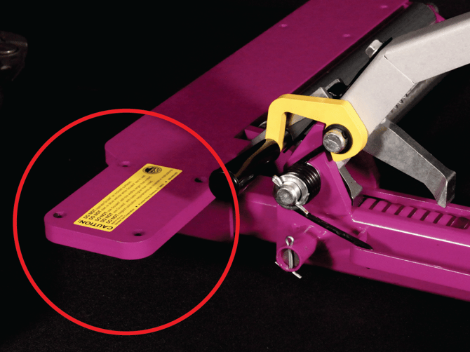
Fig. 4 – Removing casters to access the full assembly (3:20)
Remove the Cotter Pin
9. Locate the cotter pin holding the torsion spring in place.
10. Straighten the bent ends of the cotter pin using your diagonal pliers (dikes).
11. Pull the cotter pin free.
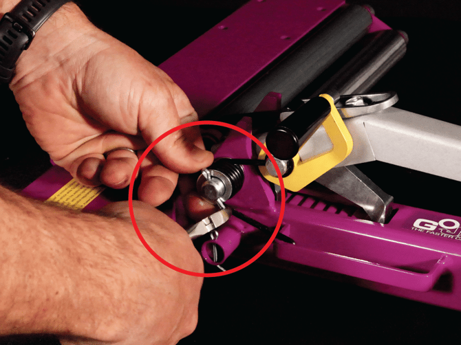
Fig. 5 – Straightening and removing the cotter pin with dikes (4:00)
Relieve Torsion Spring Tension
12. Grip the torsion spring (2017) and unhook it to relieve tension.
13. Once tension is released, push the pin through slightly — just enough to allow rotation.
14. Pull the pin out to free the assembly.
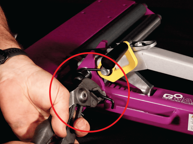
Fig. 6 – Relieving torsion spring tension and removing the pin (4:30)
Install New Parts
15. Slide the new 2009-ARM into position.
16. Ensure the 2009-WASHER is on the OUTSIDE of the cam mechanism.
17. Ensure the 2009-BOLT is oriented on top of the directional lever (see Fig. 5).
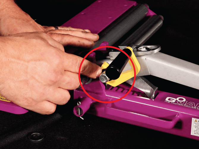
Fig. 7 – New arm installed; washer positioned on the outside (5:05)
Reinstall the Torsion Spring
Reinstalling the torsion spring can be tricky. Follow these tips:
18. Leave the outer washer and cotter pin off initially — this gives more flexibility.
19. Orient the upper pin so the spring end can be inserted.
20. Push the lower pin down slightly to allow rotation into position.
21. Before installing the washer and cotter pin, rotate the torsion spring to hook it onto the carry handle.
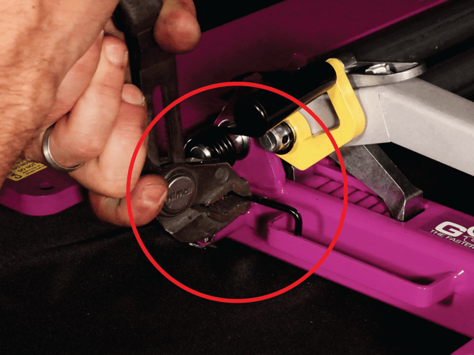
Fig. 8 – Hooking the torsion spring onto the carry handle (6:15)
Finalize the Assembly
22. Once the torsion spring is settled, tap the top pin lightly with a small hammer to seat it.
23. Slide the outer washer onto the pin.
24. Insert the cotter pin through the pin.
25. Use your diagonal pliers to bend the cotter pin ends back so it cannot back out.
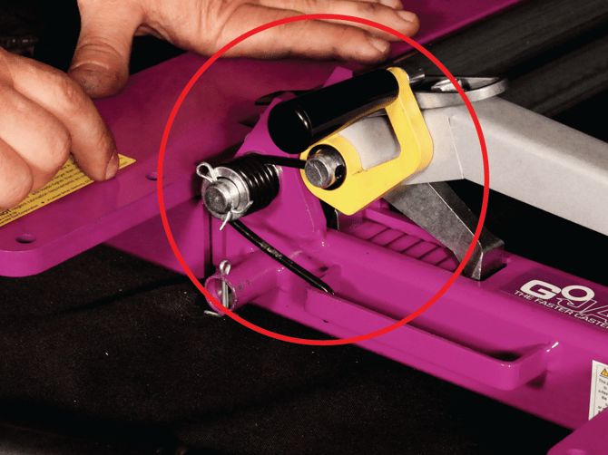
Fig. 9 – Completed cam mechanism assembly (6:55)
Final Check
Before returning the unit to service, verify the following:
- The 2009-BOLT is resting on top of the directional lever.
- The 2009-WASHER is on the outside of the 2009-ARM.
- The torsion spring is seated correctly with a washer on each side.
- The cotter pin is installed and bent so it cannot move.
Flip the directional lever to the down position and confirm the cam lever moves with it. Reinstall the casters.
Related Resources
- GoJak G9516 Parts Diagram
- G9516 Operator Manual
- For additional FAQs and repair guides, visit zendextool.com or gojak.com > Resources